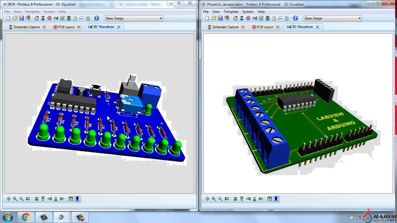

select any component as I clicked 1n4007 from devices section by clicking them once, then click in the area provided for drawing the circuit now the component is available to be place anyzhere, to place click again.Make sure you selected the little diode button.Sometimes you may have different package but you are selecting another component you need to select appropriate PCB as described here for potentiometer(variable resistor) there are many kinds of potentiometer available in market so you need to first check what is available for your then you can select appropriate design, I have mentioned here some of the potentiometers.įor this tutorial I designed a Variable Power Supply

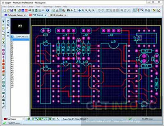
for electrolytic capacitors just tzpe cap-elec.Double click the required component and it would appear in your devices and search for other components and place them all in your devices section, some of the components might not have the PCB previews but we can add the PCB layout of them(mentioned later). Here you can check the selected options and click Finish.Ī black colored window would appear that is PCB layout tab, you can switch the tab to schematic captureĬlick on P button it stands for place, a new window would appear, In this window you can search for the components by typing exact names like 1n4007(diode) or simply type diode but if you want to make PCB you have to check that your selected component has a PCB design which is shown in PCB preview. Normally we select No firmware Project, but if we require to work with microcontrollers like 8051, Arduino we select Creat Firmware Project, and select the options accordingly, if anybody wants to know about that just write down a comment, I would guide for that.
#PROTEUS 8 PROFESSIONAL PCB LAYOUT SOFTWARE#
If you do not want PCB design just click Next otherwise Mark on create a schematic from the selected template, now you can select Generic single layer or any other layer of your requirement and then click Next, by selecting single layer if you do auto-routing then the software will do only single layer routing(bottom) if you select default and then upon selecting auto-routing the software would double layer(top & bottom layer routing). Now you need to Mark Create a schematic from the selected template then you can either select Default or you can select any templates size normally we select landscape A4, by selecting the Landscape A4 you will have a schematic window as shown in the picture 4 There you can change the Name and Path of the project after setting click N ext A new window called New Project Wizard appears


Monostable Latch Using 555 R8 100k R R9 10k L U3> 3 R 7 CV TR 555 Ton=1.When you launch Prteus click on New Project or press CTRL+N. State discussion and conclusion from the lab work. 3D PCB board conversion 4) Include the screenshot of the 3D layout from the different angles and distances, top and also bottom layer of the board in your report to show all the copper track as well as the components arrangement. 3) After that, convert your PCB layout into 3D view as shown in Figure 2. Explain the process of creating the layout and the layout itself. 2) Screenshot / print screen your PCB layout and include it in your lab report. Make all the connections based on the schematics and make sure there are no errors. 1040 Figure 1: Image of Veroboard and Lavout PCB Procedure: 1) Based on the circuit constructed in the Lab 1, convert the circuit schematic into PCB layout. One is Veroboard PCB and another one is layout PCB. This is a circuit board with printed copper layout connections. But what is PCB? Why we are using this PCB? We want to know about all these things as an electronic engineer. Introduction: Generally, we are listening the words PCB's, PCB layout, PCB designing. To be able to establish the connection between components in the PCB layout drawing and troubleshoot for any errors. To create a PCB layout drawing of an electronic circuit in a simulation software. Transcribed image text: PCB LAYOUT DESIGN OF A MONOSTABLE LATCH USING 555-TIMER Objectives: 1.


 0 kommentar(er)
